How a Micro Coaxial Assembly Is Built: Six Steps That Decide Yield
A 40-pin, 46 AWG micro coax assembly is not one product — it is 40 terminations, 40 shields, two connector shells and a length tolerance, all inside a 300 mm envelope. Most quality problems I see in incoming samples come from one of six steps, and each step has a dominant failure mode that the next step tends to hide.
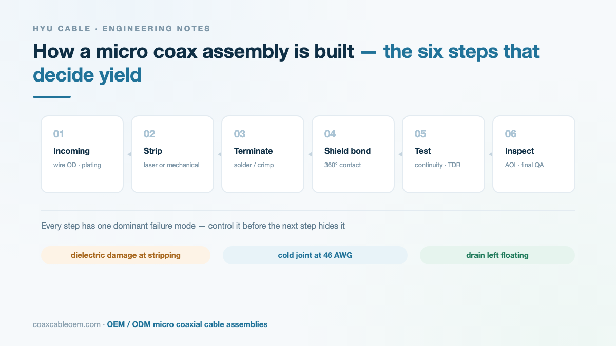
Here is how we build them, and what we control at each station.
1. Incoming inspection
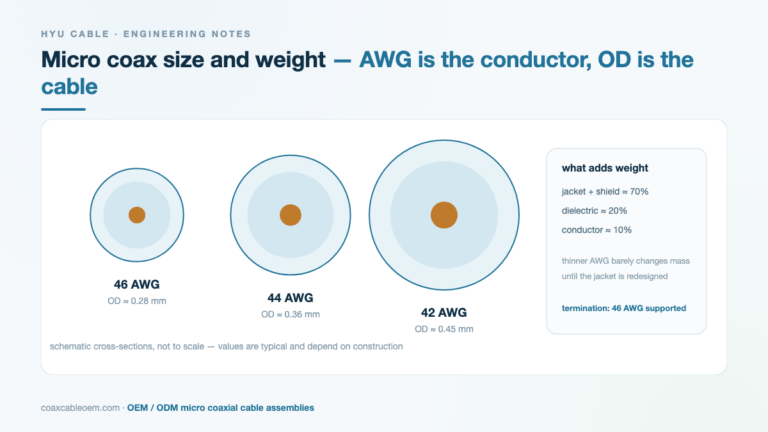
We measure wire outer diameter, conductor resistance and connector plating before anything is cut. A batch of 46 AWG wire that is 5% out of tolerance changes the crimp height and the impedance. Plating thickness matters more than most people expect: thin gold on the contact oxidises after a few hundred mating cycles.
2. Stripping
At 46 AWG the dielectric is a few tenths of a millimetre thick. Mechanical stripping is fast but can nick the centre conductor; laser stripping is clean but needs the parameters to match the insulation material. Either way, the failure mode is invisible: a damaged dielectric shows up later as an impedance bump, not as an open circuit.
3. Termination
Hot-bar or pulse-heat soldering is standard for these connectors. The two things we control are temperature profile and dwell time. Too little heat gives a cold joint that passes continuity but fails thermal cycling; too much heat melts the insulator and shifts the contact. Every new connector suffix gets its own profile — they are not interchangeable.
4. Shield bonding
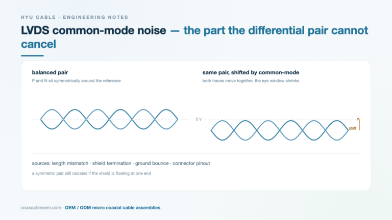
This is where most of the electrical performance is decided. A 360° crimp or solder bond to the shell gives a low-inductance path. A pigtail gives you a few nanohenries you did not budget for, and it radiates. We check bond resistance on a sample from each lot.
5. Jacket and strain relief
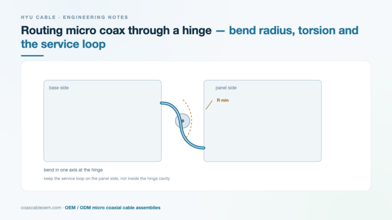
The bundle needs a transition that spreads the bend away from the solder joints. Without it, the assembly fails at the connector after a few hundred flex cycles, and the customer blames the connector. We specify the bend radius on the drawing and mould or heat-shrink accordingly.
6. Test and inspection
100% continuity and hipot are the baseline. For high-speed links we add insertion loss or TDR on a sample basis, and we keep the trace with the shipment. Visual inspection at 10–20x checks for solder bridges, shield strands and jacket damage.
| Step | Dominant failure mode | Control |
|---|---|---|
| Incoming | Wire OD or plating out of spec | Per-lot measurement, certificate review |
| Stripping | Damaged dielectric or nicked conductor | Laser parameters, pull test sample |
| Termination | Cold joint or melted insulator | Profile per connector suffix, X-ray sample |
| Shield bond | Pigtail instead of 360° contact | Bond resistance check, visual |
| Jacket | Bend concentrated at the joint | Transition design, bend radius on drawing |
| Test | Passing continuity but failing at rate | Insertion loss / TDR sample, traceability |
What this means for your drawing
If your drawing specifies only connector, pin count and length, the supplier has to choose the rest. That is where samples diverge between suppliers. Adding four lines — shield bond method, bend radius, test method and acceptable insertion loss — removes most of the ambiguity.
Our 8-point RFQ checklist covers the full list, and the custom assembly range shows the connector families we build daily.
FAQ
Do you test every assembly for insertion loss? Not by default — it is a sampling test unless the drawing requires 100%. Full testing is available but adds cost and lead time.
Can you match another supplier’s sample? Yes, if you send the sample and the drawing. We measure the shield bond, length and jacket transition before quoting.
What is the most common cause of field failure? Bending at the connector joint, usually because the harness was installed without a strain relief.