Micro Coaxial Cable Assemblies for AI Glasses and AR Headsets
Designing micro coaxial assemblies for AI glasses and AR headsets: 0.3/0.4/0.5 mm pitch choice, hinge routing rules, EMI grounding strategy and a prototype DFM checklist.


Designing micro coaxial assemblies for AI glasses and AR headsets: 0.3/0.4/0.5 mm pitch choice, hinge routing rules, EMI grounding strategy and a prototype DFM checklist.
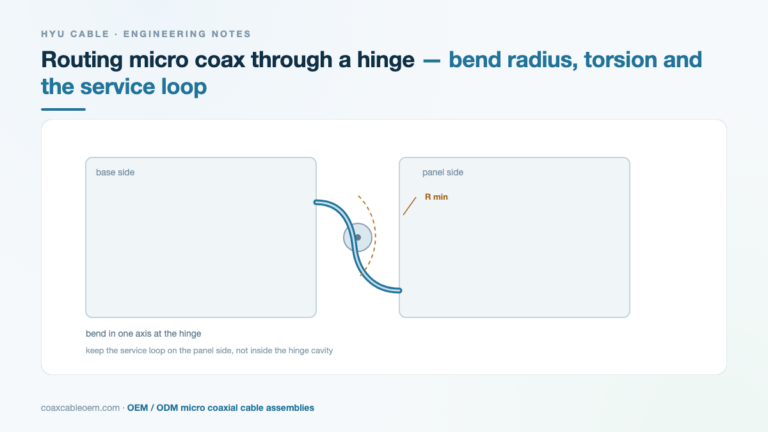
Hinges and rotating joints are where micro coax assemblies fail in the field. Bend radius, torsion, service loops and the tests that expose them.
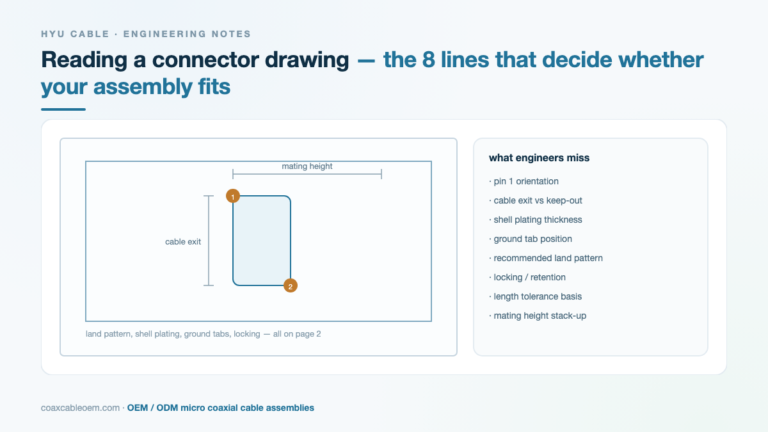
Most fit problems are decided before the cable is built. Eight items on a micro coaxial connector drawing that engineers routinely skip.
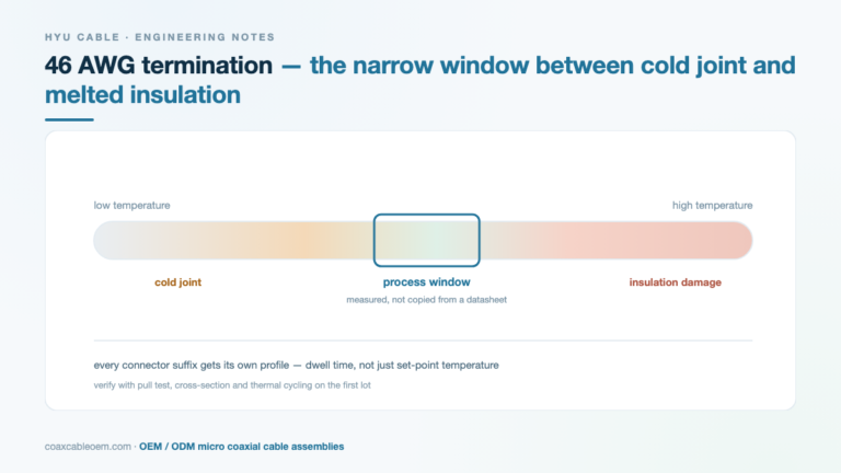
At 46 AWG the soldering window between a cold joint and a melted insulator is narrow. How to find it on your own line instead of copying a profile.
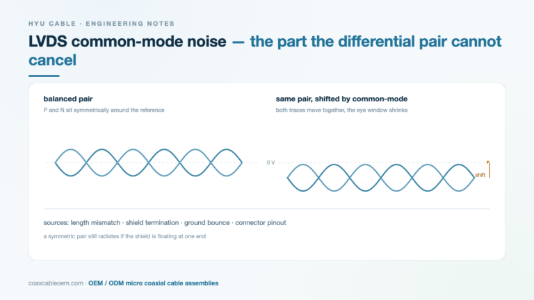
A differential pair cancels differential noise, not common-mode noise. The practical sources in LVDS links, and the fixes that actually change the measurement.
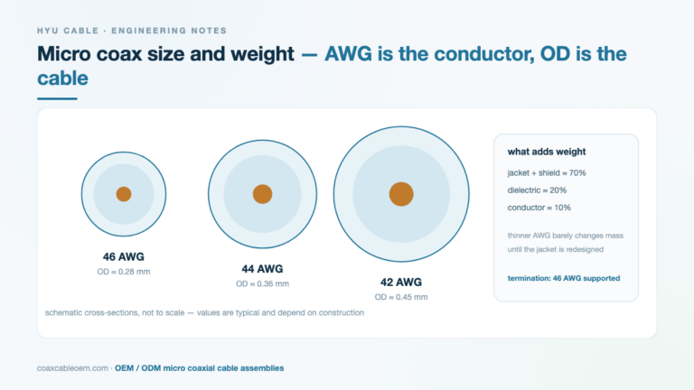
AWG describes the conductor, not the cable. A practical guide to outer diameter, weight and the real limits of 46 AWG micro coaxial constructions.

Ultrasound probe cables rarely fail at the connector. They fail at the housing exit, where bending, disinfection and autoclave cycles meet. Here is what to specify.
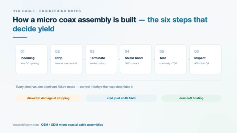
From incoming inspection to final test: the six production steps that determine micro coaxial assembly yield, and the failure mode each step controls.
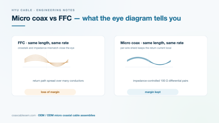
An engineer’s note on why a micro coaxial link keeps its eye open where an FFC closes it: return path, impedance control, crosstalk and shield termination.
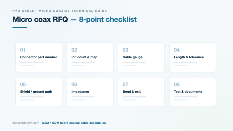
The eight details that let a cable supplier quote accurately and build the assembly right the first time: connector series, pin map, length, shielding, impedance, bend radius, testing and documentation.