Micro Coaxial Cable Assemblies for AI Glasses and AR Headsets
AI glasses and AR headsets fail in the field for a small set of reasons, and most of them start at the cable. The display module needs a high-speed link, the camera needs another, the hinge has to survive tens of thousands of open-close cycles, and all of it has to fit inside a frame that weighs less than 50 grams. Micro coaxial assemblies are the usual answer — but only if the pitch, routing and shielding are decided together, early.
Why eyewear strains a cable more than a phone does
A phone gives a cable a fixed cavity and a single flex point at the hinge. Eyewear gives it three constraints at once:
- Volume: the temple arm is typically 3–5 mm thick, so the assembly plus connector has to fit inside a channel narrower than a USB-C plug.
- Cycles: glasses are opened and closed far more often than a laptop lid. A frame rated for two years of daily use can see 20,000–50,000 hinge cycles, each one bending the same short cable segment.
- Antenna proximity: Wi-Fi, Bluetooth and GNSS antennas sit in the same temple, often within 10 mm of the display link. Any leakage from the cable couples straight into the receiver.
That combination is why micro coax, rather than shielded FFC, dominates this category: the outer conductor shields along the whole length, and impedance stays stable when the cable is bent. The trade-off is assembly difficulty at 0.3 mm pitch.
Pitch selection: the first decision that locks everything else
| Pitch | Typical pin count | Mated height | Best fit in eyewear | Assembly difficulty |
|---|---|---|---|---|
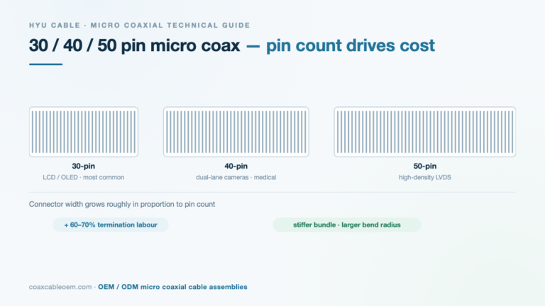
| 0.3 mm | 26–50 | Lowest | Display link in the thinnest temple arm; dual-camera modules | High — fine wire, tight solder window |
| 0.4 mm | 30–51 | Medium | Camera + IMU + audio combined on one connector | Medium |
| 0.5 mm | 30–51 | Highest | Prototype builds, larger frames, easier rework | Low |
Rule of thumb we apply in DFM review: if the frame wall is under 4 mm and the link runs at 2 Gbps or above, start at 0.3 mm. If the design still has mechanical margin, 0.4 mm gives you a wider process window for the same signal quality. Moving from 0.5 mm to 0.3 mm late in a program usually means new tooling, new fixtures and a re-qualification cycle.
More detail on the trade-offs: 0.3 vs 0.4 vs 0.5 mm pitch compared.
Hinge routing: where most failures are born
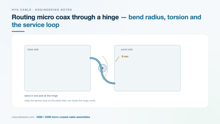
In our experience with eyewear prototypes, hinge fatigue is the single most common mechanical failure, and it is almost always a routing decision rather than a cable defect. Four rules:
- Bend radius: keep ≥ 5× the cable OD for dynamic flex. A 0.36 mm OD cable therefore needs roughly 1.8 mm minimum radius — easy on paper, hard inside a 4 mm arm once the connector body is accounted for.
- Neutral axis: route the cable so the hinge pivot sits near the middle of the bend, not at either end. Bending at a fixed point concentrates fatigue in one 2–3 mm segment.
- No sharp transitions: a hard edge or a step in the frame acts as a stress riser. Use a small radius insert or a relieved channel.
- Strain relief at both ends: the connector should not carry the bending load. Potting or a short heat-shrink collar at the pigtail end adds cycle life cheaply.
Routing detail and a worked example: micro coax hinge routing.
EMI: shielding is necessary, grounding strategy is what matters
A micro coax assembly has a shield, but the shield only works if the return path is defined. Three configurations, in order of effectiveness for eyewear:
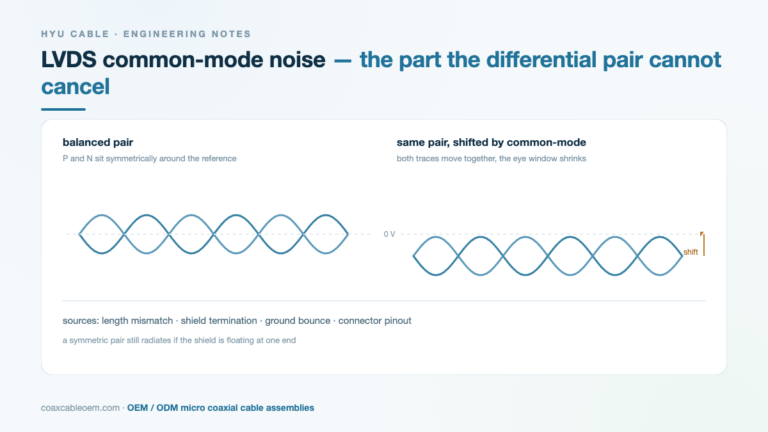
- Ground both ends to a common reference — best for high-speed display links. Requires care so the two grounds do not create a loop through the frame.
- Ground at the receiver end only — acceptable for camera links and reduces loop risk, at the cost of some low-frequency shielding.
- Floating shield with a pigtail — works only when the cable is short and the antenna is far away; in eyewear it usually is not far enough.
Practical additions that cost little: a ferrite-loaded jacket on the segment nearest the antenna, and separating the display cable from the antenna feed by at least 8–10 mm wherever the layout allows. If the frame forces them together, expect desense and budget for shielding iteration.
Weight: the invisible spec
Every gram in the temple becomes torque on the wearer’s ear. Two levers, both cheap:
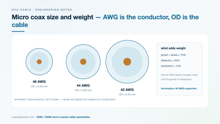
- Go one AWG finer where current allows. 46 AWG micro coax reduces conductor and insulation mass meaningfully over 44 AWG across a 100 mm run.
- Shorten the run. A 10 mm reduction per side is worth more than most component swaps.
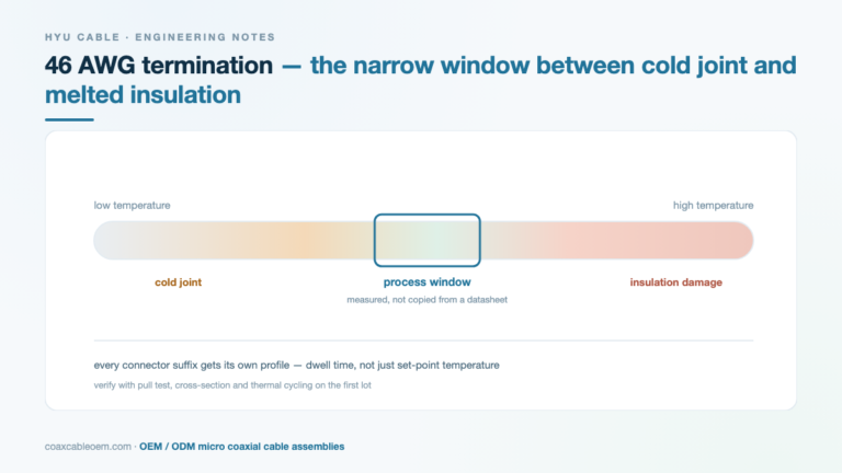
Finer wire narrows the termination window, though — see 46 AWG termination temperature window before committing to it.
Prototype-to-production checklist
| Stage | What to confirm |
|---|---|
| Before tooling | Connector series and pitch fixed, drawing with pin assignment, bend radius and routing envelope agreed |
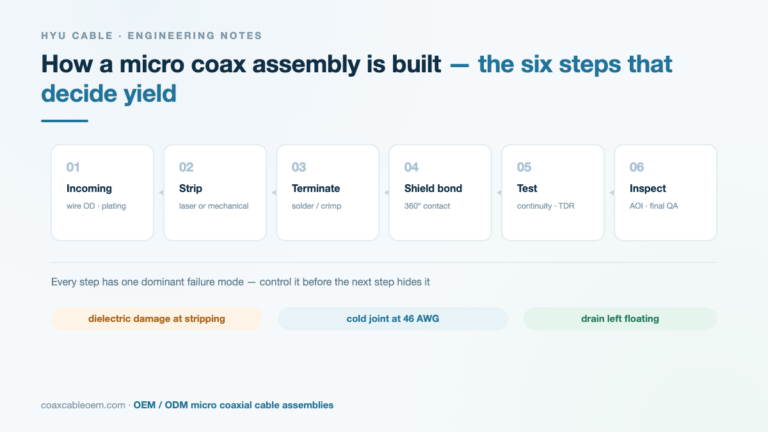
| First articles | Continuity, hipot, impedance sample check, insertion loss at target frequency, visual at 20× |
| Reliability | Hinge cycling to target count, thermal cycling, pull test on the pigtail |
| Production | In-process electrical test on 100%, fixture-based bend check, lot traceability on cable and connector |
A full RFQ package checklist is here: micro coaxial assembly RFQ checklist.
What we build for this category
HYU Cable produces custom micro coaxial assemblies around the connector families commonly used in eyewear and head-mounted devices, including I-PEX 20453 / 20454 / 20496 / 20679, Hirose DF56 and DF80, JAE FI-RE series and KEL USL20. Send a drawing with pin assignment and routing envelope, and we return DFM feedback before quoting.
Connector part-number lookup: 190+ part numbers across I-PEX, Hirose, JAE and KEL.
FAQ
Is micro coax overkill for a camera link under 1 Gbps?
Often yes. Below roughly 1 Gbps with a short run, shielded FFC is cheaper and easier to assemble. Micro coax earns its cost when the link is high-speed, the cable is bent repeatedly, or the antenna is close.
Can a 0.3 mm pitch assembly be reworked in the field?
Not realistically. Rework at that pitch requires a microscope and a dedicated fixture; field replacement means swapping the whole assembly. Design the connector location so the assembly can be replaced as a unit.
How many hinge cycles should we specify?
Base it on daily use, not on a round number. Two years of 30 opens per day is about 22,000 cycles; specifying 50,000 gives margin for test-to-failure data and customer misuse.
Does a longer cable always mean more loss?
Loss scales with length, but in eyewear the dominant contributors are usually connector transition and impedance discontinuity at the pigtail, not the cable itself. Fix the transition first.